


Maximum 100mΩ at initial value.
Test Current: 1A, Open Circuit Test Voltage: 6VDC.
By using Voltage Drop Method.
|
Safety Standard: CQC TUV |
|
| Contact Gap | 0.3mm Minimum |
| Contact Resistance |
Maximum 100mΩ at initial value. |
| Contact Capacity |
16Amps at 250VAC Cosφ=1. |
| Rated Voltage | 3VDC | 5VDC | 6VDC | 9VDC | 12VDC | 24VDC | 48VDC |
| Nominal Current( mA± 10%) | 176/240 | 106/139 | 88/120 | 56/78 | 44/60 | 22/30 | 11/15 |
| Rated Power Consumption (± 10%) | 0.54W/0.72W | ||||||
| Coil Resistance | 17/12.5 | 47/36 | 68/50 | 160/115 | 275/200 | 1100/820 | 4170/3300 |
| Pull In Voltage |
≦ (Contact operating voltage when voltage is gradually applied. It is 75% of the Rated Voltage) V DC |
||||||
| Drop Out Voltage |
≧ (Contact breaking voltage when rated voltage is gradually reduced. It is 10% of the Rated Voltage) VDC |
||||||
| Max. Allowable Voltage |
(140% of the Rated Voltage) V DC |
||||||
| Operate Time | 15milliseconds Maximum when rated Voltage is applied. | ||||||
| Release Time | 5milliseconds Maximum when rated Voltage is suddenly cut off. | ||||||
| Coil Temperature Rise |
40℃ Maximum.Maximum Allowable Voltage is applied to Coil while no load should be applied to Contacts, then the temperature should be measured when the value is stabilized. Environment temperature should not be included in |
||||||
| Life Expectancy | Electrical Life:100,000 operations Minimum at16A/250VAC Cosφ=1. 100,000 operations Minimum at 16A/30VDC Rated Voltage is applied |
| Mechanical Life:10,000,000 operations Minimum at No Load condition | |
| Maximum Operating Frequency :Electrical: 30 operations/minute. Mechanical: 300 operations/minute. | |
| Dielectric Strength | Between Contacts:1000VAC at Test Frequency 50/60 Hz, Leakage Current: 1mA for 1 minute |
| Between Coil & Contact:5000VAC at Test Frequency 50/60 Hz, Leakage Current: 1mA for 1 minute | |
| Insulation Resistance | A Voltage of 500VDC should be applied after which measurement shall be made |
| Vibration | Endurance I: The Coil shall be maintained under not energized condition, double amplitude 1.5 mm, the entire frequency range changes from 10 to 55 Hz then returns to 10 Hz shall be made in 1 minute. This motion shall be applied for a period of 2 hours in each of 3 mutually perpendicular axis (a total of 6 hours) There should not be any deformations in construction and in appearance, while the Electrical Specifications should be fulfilled after the test. |
| Endurance II (Error Operation):The Coil shall be maintained under energized condition, double amplitude 1.5 mm, the entire frequency range changes from 10 to 55 Hz then returns to 10 Hz shall be made in 1 minute. This motion shall be applied for a period of 5 minutes in 3 mutually perpendicular axis. Malfunction is not allowed during the test (contact breaking time should be less than 1 millisecond) In addition, there should not be any deformations in construction and in appearance while the Electrical Specifications should be fulfilled after the test | |
| Shock | Endurance I:Peak Acceleration: 1000m/s2 The Coil shall be maintained under not energized condition, 5 successive shocks shall be applied in 3 mutually perpendicular axis. There should not be any deformations in construction and in appearance while the Electrical Specifications should be fulfilled after the test. |
| Endurance II (Error Operation:Peak Acceleration: 100m/s2 The Coil should be maintained under energized condition, 2 successive shocks shall be applied in 3 mutually perpendicular axis. Malfunction is not allowed during the test (contact breaking time should be less than 1 millisecond) In addition, there should not be any deformations in construction and in appearance while the Electrical Specifications should be fulfilled after the test |
| Temperature Range | Operating Temperature Range:-40 to + 70°C Operating temperature range is the range of ambient temperature of which the Relay can be operated continuously within operative voltage range of coil (no condensation of water drops under low temperature condition) |
| Storage Temperature Range:-30 to + 70°C. Storage temperature range is the range of ambient temperature of which the Relay can be stored without damages (no condensation of water drops under low temperature condition). Conditions are as specified elsewhere in these specifications |
|
| Humidity Range | 40~85% RH |
| Cold Resistance | Cold Resistance in Use:Relay should be kept in temperature chamber at -40 ± 2°C for two hours that no current or voltage shall be supplied to Relay. Such condition shall be maintained while the rated voltage is supplied to Relay, then the Relay shall operate normally. (No condensation of water drops under low temperature condition) |
| Storage Cold Resistance:Relay should be kept in temperature chamber at -40 ± 2°C for 72 hours. Then the Relays shall be maintained at standard atmospheric condition for 1 to 2 hours after which measurement shall be made. Construction, Relay operation, Insulation Resistance and Dielectric Strength shall satisfy the specification requirements. (No condensation of water drops under low temperature condition) | |
| Heat Resistance | Heat Resistance in Use:Relay should be kept in temperature chamber at 70 ± 2°C for two hours that rated Voltage should be supplied to Coil while rated Current should be supplied to Contacts. Such condition shall be maintained while the rated voltage is supplied to Relay, then Relay shall operate normally |
| Storage Heat Resistance:Relay should be kept in temperature chamber at 70 ± 2°C for 16 hours. Then the Relays shall be maintained at standard atmospheric condition for 1 to 2 hours after which measurement shall be made. Construction, Relay operation, Insulation Resistance and Dielectric Strength shall satisfy the specification requirements | |
| Moisture Resistance |
Relay should be kept in temperature chamber at 40 ± 2°C (90~95% RH) for 48 hours. Then the Relays shall be maintained at standard atmospheric condition for 1 to 2 hours after which measurement shall be made. Construction, Relay operation, Insulation Resistance, Dielectric Strength shall satisfy the specification requirements |
| Terminal Strength |
A load of 300g should be applied to the Terminal for one minute in horizontal direction. There should not be any looseness or bending of Terminals |
| Soldering Dip Test |
The front 3 mm of Terminal should be immersed for 3 ± 0.5 seconds at 230 ± 5°C. Soldered area must be minimum 90% of the soldering surface |
| Soldering Heat Resistance |
When the Terminal are immersed into soldering bath at 350 °C for 3 seconds, the Relay shall satisfy all electrical and mechanical specifications and must not have excessive change in outside appearance |
Weight:Approx.14g
Sample Test Method:GB2828-2000 Level – General II, AQL 0.4
| HK14FH | -DC 12V -S X X X X |
| Special Request Code | G:RoHS |
| Mounting Termination | 无:PCB |
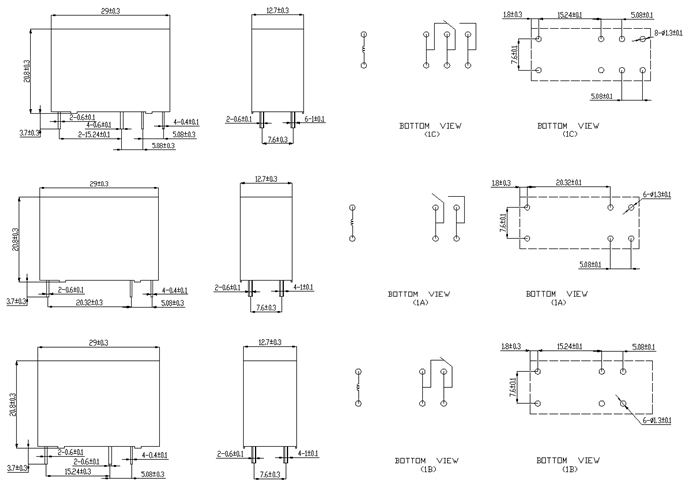
| Contact Form | NIL: 1C 1A 1B |
| Coil Power | NIL:0.72W H:0.53W |
| Type Of Sealing | NIL:Flow Solder Type S:Plastic Sealed Type |
| Coil Voltag | 3V、5V、6V、9V、12V、24V、48V |
| CoilType | DC:DC |
| Type | HK14FH |
| Type | Inner packaging method | Carton Size | The total amount | Net weight (Kg) | Gross weight (Kg) |
| L * W * H | |||||
| HK14FH | 25 / tube (10 tubes per box, a total of 4 boxes) | 39*38*18 | 1000/box | 12.7 | 15.5 |